
Uneven Clicks using 555 IC
This circuit produces two clicks then a short space before two more clicks etc. Changing the voltage on pin, 5 via the diode, adjusts the timing of the chip.
This circuit uses the 1N4148 diode to regulate the voltage on pin 5 of 555 IC to produce uneven click sound effect.
COMPONENTS USED :
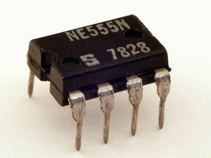
1.one 555 IC
2.one 1N4148 Diode
3.one 47K resistance
4.two 10uF Electrolytic capacitance
5.one 8ohm speaker
6.one 6-12V power supply

STEPS :
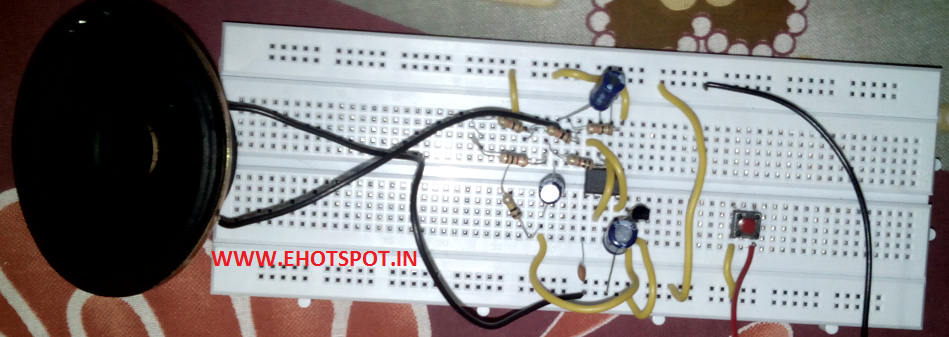
1.Place 555 IC on breadboard.
2.Connect pin 2 to pin 6.
3.Connect pin 4 to pin 8.
4.Connect pin 1 to ground.
5.Connect pin 8 toVCC.
6.Connect pin 2 with positive side of a 10uF cap,connect negative side to ground.
7.Connect a 47K resistance between pin 2 and pin 3.
8.Connect the 1N4148 diode between pin 5 and pin3.
9.Connect long leg of another 10uf with pin3 .
10.Connect shorter leg of cap above with one terminal of speaker,connect another terminal of speaker to ground.
11.Turn on power supply and Enjoy..!

(NOTE - i didnt have a 47K resistance so i used a combination of resistances to make up 47K resistance )


This circuit uses the 1N4148 diode to regulate the voltage on pin 5 of 555 IC to produce uneven click sound effect.
COMPONENTS USED :
1.one 555 IC
2.one 1N4148 Diode
3.one 47K resistance
4.two 10uF Electrolytic capacitance
5.one 8ohm speaker
6.one 6-12V power supply
STEPS :
1.Place 555 IC on breadboard.
2.Connect pin 2 to pin 6.
3.Connect pin 4 to pin 8.
4.Connect pin 1 to ground.
5.Connect pin 8 toVCC.
6.Connect pin 2 with positive side of a 10uF cap,connect negative side to ground.
7.Connect a 47K resistance between pin 2 and pin 3.
8.Connect the 1N4148 diode between pin 5 and pin3.
9.Connect long leg of another 10uf with pin3 .
10.Connect shorter leg of cap above with one terminal of speaker,connect another terminal of speaker to ground.
11.Turn on power supply and Enjoy..!
(NOTE - i didnt have a 47K resistance so i used a combination of resistances to make up 47K resistance )


