• Arduino

    Learn about Arduino and make various interesting projects using Arduino...

    Read More
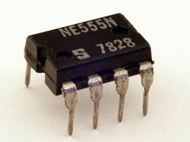
  • 555 IC

    Learn about 555 IC and make various interesting projects using 555 IC...

    Read More
  • Basic Electronics

    Learn about Basic Electronics and various electronic components and their working...

    Read More

what is Arduino ?

Arduino is an open-source electronics prototyping platform based on flexible, easy-to-use hardware and software. It's intended for artists, designers, hobbyists, and anyone interested in creating interactive objects or environments. This Google Code project is the home for the development of the Arduino platform. For more information on using Arduino, see the Arduino homepage.

The Arduino software consists of a development environment (IDE) and the core libraries. The IDE is written in Java and based on the Processing development environment. The core libraries are written in C and C++ and compiled using avr-gcc and AVR Libc. The source code for Arduino is now hosted on GitHub.

“Arduino is a single-board microcontroller designed to make the process of using electronics in
multidisciplinary projects more accessible. The hardware consists of a simple open-source hardware board designed around an 8-bit Atmel AVRmicrocontroller, though a new model has been designed around a 32-bit Atmel ARM.
The software consists of a standard programming language compiler and a boot loader that executes on the microcontroller.

 The Arduino board is made up of an Atmel AVR microprocessor, a crystal or oscillator (a crude clock that sends time pulses at a specified frequency to enable it to operate at the correct speed) and a 5V voltage regulator. (Some Arduinos may use a switching regulator, and some, like the Due, are not 5 volt). Depending on what type of Arduino you have, it may also have a USB socket to enable it to be connected to a PC or Mac to upload or retrieve data. The board exposes the microcontroller’s I/O (input/output) pins to enable you to connect those pins to other circuits or to
sensors, etc.
To program the Arduino (make it do what you want it to), you also use the Arduino IDE, which is a piece of free software that enables you to program in the language that the Arduino understands. In the case of the Arduino, the language is based on C/C++ and can even be extended through C++ libraries. The IDE enables you to write a computer program, which is a set of step-by-step instructions that you then upload to the Arduino. Your Arduino will then carry out those instructions and interact with whatever you have connected to it. In the Arduino world, programs
are known as “sketches”.

555 Timer LED Flashing circuit

This circuit uses the 555 timer in an Astable operating mode which generates a continuous output via Pin 3 in the form of a square wave. This turns the LED (D1) on and off. The speed at which the LED (D1) is turned on and off is set by the values of R1 and R2.

Components Required :

1x - 555  Timer IC
1x - LED (Any color )
1x - 470K Resistor
2x - 1K Resistor
1x - 1uF Electrolytic Capacitor
1x - 9V Voltage Battery


STEPS : 

1. Place the IC on your breadBoard , remember to put it in correct way else IC will burn.


2. Now connect the pin 1 to ground.
3. Connect the pin 2 with 6 and pin 4 with 8
4. Connect 1uF cap between pin 2 and ground, place long leng of capacitor towards the pin 2 and short leg towards ground.
5. Connect a resistance of 470K from pin 2 to 7 and connect a 1K resistance from pin 7 to VCC.
6. Connect pin 8 to VCC.
7. Connect a resistance of 1K from pin 3 to the longer leg of LED , then connect the shorter leg of LED to Ground.
8. Do not connect anything to pin 5 and leave it as it is.
9. Now just connect the Battery and enjoy the show.


Soldering on a perfboard

Carefully note the position of a component on your bread- board, and then move it to the same relative position on the perfboard, poking its wires through the little holes. Turn the perfboard upside down, make sure that it’s stable, and examine the hole where the wire is poking through, as shown in Figure below.

 A copper trace surrounds this hole and links it with others. Your task is to melt solder so that it sticks to the copper and also to the wire, forming a solid, reliable connection between the two of them. Take your pencil-style soldering iron in one hand and some solder in your other hand. Hold the tip of the iron against the wire and the copper, and feed some thin solder to their intersection. After two to four seconds, the solder should start flowing.


Allow enough solder to form a rounded bump sealing the wire and the copper, as shown in Figure below :


Wait for the solder to harden thoroughly, If all is well, snip the protruding wire with your cutters. See Figure below :

PerfBoard Errors :

 TOO MUCH SOLDER :

If the joint is thin, the wire can break free from the solder as it cools. Even a microscopic crack is sufficient to stop the circuit from working. In extreme cases, the solder sticks to the wire, and sticks to the copper trace around the wire, yet doesn’t make a solid bridge con- necting the two, leaving the wire encircled by solder yet untouched by it, as shown in Figure below. 


You may find this undetectable unless you observe it with magnification. You can add more solder to any joint that may have insufficient solder, but be sure to reheat the joint thoroughly. 


COMPONENTS PLACED INCORRECTLY :

It’s very easy to put a component one hole away from the position where it should be. It’s also easy to forget to make a connection. I suggest that you print a copy of the schematic, and each time you make a connection on the perforated board, you eliminate that wire on your hardcopy, using a highlighter.

All about Diodes

A diode is a very early type of semiconductor. It allows electricity to flow in one direction, but blocks it in the opposite direction. (A light-emitting diode is a much more recent invention.) Like an LED, a diode can be damaged by revers- ing the voltage and applying excessive power, but most diodes generally have a much greater tolerance for this than LEDs. The end of the diode that blocks positive voltage is always marked, usually with a circular band, while the other end remains unmarked. Diodes are especially useful in logic circuits, and can also convert alternating current (AC) into direct current (DC).

A Zener diode is a special type that  blocks current completely in one direction, and also blocks it in the other direction until a threshold voltage is reached.

Signal diodes are available for various different voltages and wattages. Like any semiconductor, they can overheat and burn out if they are subjected to mistreatment. The schematic symbol for a diode has only one significant variant: sometimes the triangle is outlined instead of filled solid black (see in Figure below).


What are capacitors?

DC current does not flow through a capacitor, but voltage can accumulate very quickly inside it, and remains after the power supply is disconnected. Figures below may help to give you an idea of what happens inside a capacitor when it is fully charged.


In most modern electrolytic capacitors, the plates have been reduced to two strips of very thin, flexible, metallic film, often wrapped around each other, separated by an equally thin insulator. Disc ceramic capacitors typically consist of just a single disc of nonconductive material with metal painted on both sides and leads soldered on. The two most common varieties of capacitors are ceramic (capable of storing a relatively small charge) and electrolytic (which can be much larger). Ceramics are often disc-shaped and yellow in color; electrolytics are often shaped like miniature tin cans and may be just about any color.

Ceramic capacitors have no polarity, meaning that you can apply negative volt- age to either side of them. Electrolytics do have polarity, and won’t work unless you connect them the right way around. The schematic symbol for a capacitor has two significant variants: with two straight lines (symbolizing the plates inside a capacitor), or with one straight line and one curved line, as shown in below.


 When you see a curved line, that side of the capacitor should be more negative than the other. The schemat- ic symbol may also include a + sign. Unfortunately, some people don’t bother to draw a curved plate on a polarized capacitor, yet others draw a curved plate even on a nonpolarized capacitor.

All about Switches

When you flip a toggle switch  it connects the center terminal with one of the outer terminals. Flip the switch back, and it connects the center terminal with the other outer terminal, as shown in Figure below:

 The center terminal is called the pole of the switch. Because you can flip, or throw, this switch to make two possible connections, it is called a double-throw switch.  Some switches are on/off, meaning that if you throw them in one direction they make a contact, but in the other direction, they make no contact at all. Most of the light switches in your house are like this. They are known as single-throw switches. A single-pole, single-throw switch is abbreviated SPST.

 Some switches have two entirely separate poles, so you can make two separate connections simultaneously when you flip the switch. These are called double-pole switches. Check the photographs below


SPARKING :

 When you make and break an electrical connection, it tends to create a spark. Sparking is bad for switch contacts. It eats them until the switch doesn’t make a reliable connection anymore. For this reason, you must use a switch that is appropriate for the voltage and amperage that you are dealing with. Electronic circuits generally are low-current, and low-voltage, so you can use almost any switch, but if you are switching a motor, it will tend to suck an initial surge of cur- rent that is at least double the rating of the motor when it is running constantly. You should probably use a 4-amp switch to turn a 2-amp motor on and off.

Checking a switch :

You can use your meter to check a switch. Doing this helps you find out which contacts are connected when you turn a switch one way or the other.
 Set your meter to measure ohms, and touch the probes to the switch terminals while you work the switch. This is a hassle, though, because you have to wait while the meter makes an accurate measurement. When you just want to know whether there is a connection, your meter has a "continuity tester" setting. It beeps if it finds a connection, and stays silent if it doesn’t.


Exploring Potentiometers

Potentiometers come in various shapes and sizes, but they all do the same thing: they allow you to vary voltage and current by varying resistance.

Most potentiometers are held together with little metal tabs. You should be able to grab hold of the tabs with your wire cutters or pliers, and bend them up and outward. If you do this, the potentiometer should open up as shown


Depending whether you have a really cheap potentiometer or a slightly more high-class version, you may find a circular track of conductive plastic or a loop of coiled wire. Either way, the principle is the same. The wire or the plastic possesses some resistance (a total of 2K ), and as you turn the shaft of the potentiometer, a wiper rubs against the resistance, giving you a shortcut to any point from the center terminal.

To test your potentiometer, set your meter to measure resistance (ohms) and touch the probes while turning the potentiometer shaft to and fro, as shown below

How big a resistor does an LED need

Suppose that we use an LED with Maximum of 3 volts, and a safe current of 20mA.

 I’m going to limit it to 2.5 volts, to be on the safe side. We have 6 volts of battery power. Subtract 2.5 from 6 and we get 3.5. So we need a resistor that will take 3.5 volts from the circuit, leaving 2.5 for the LED.

The current flow is the same at all places in a simple circuit. If we want a maximum of 20mA to flow through the LED, the same amount of current will be flowing through the resistor.


 Now we can write down what we know about the resistor in the circuit. Note that we have to convert all units to volts, amps, and ohms, so that 20mA should be written as 0.02 amps:

 V = 3.5 (the potential drop across the resistor)
 I = 0.02 (the current flowing through the resistor)

We want to know R, the resistance. So, we use the version of Ohm’s Law that puts R on the left side: R= V/I

Now plug in the values:
R = 3.5/0.02

Run this through your pocket calculator if you find decimals confusing. The answer is:
R = 175Ω

It so happens that 175Ω isn’t a standard value. You may have to settle for 180 or 220Ω, but that’s close enough.

How much voltage does a wire consume?

 Normally, we can ignore the resistance in electric wires, such as the little leads of wire that stick out of resistors, because it’s trivial. However, if you try to force large amounts of current through long lengths of thin wire, the resistance of the wire can become important.

How important? we can use Ohm’s Law to find out.
Suppose that a very long piece of wire has a resistance of 0.2Ω. And we want to run 15 amps through it. How much voltage will the wire steal from the circuit, because of its resistance?
 Once again, you begin by writing down what you know:
R = 0.2
I = 15

 We want to know V, the potential difference, for the wire, so we use the version of Ohm’s Law that places V on the left side:

V = I × R

 Now plug in the values: V = 15 × 0.2 = 3 volts Three volts is not a big deal if you have a high-voltage power supply, but if you are using a 12-volt car battery, this length of wire will take one-quarter of the available voltage. Now you know why the wiring in automobiles is relatively thick—to reduce its resistance well below 0.2Ω.


Lightening an LED

 An old-fashioned lightbulb wastes a lot of power by converting it into heat. LEDs are much smarter: they convert al- most all their power into light, and they last almost indefinitely—as long as you treat them right!
An LED is quite fussy about the amount of power it gets, and the way it gets it. Always follow these rules:
• The longer wire protruding from the LED must receive a more positive volt- age than the shorter wire.

• The voltage difference between the long wire and the short wire must not exceed the limit stated by the manufacturer.

• The current passing through the LED must not exceed the limit stated by the manufacturer.

What happens if you break these rules? Well, we’re going to find out!
Make sure you are using fresh batteries. You can check by setting your multi- meter to measure volts DC, and touching the probes to the terminals of each battery. You should find that each of them generates a pressure of at least 1.5 volts. If they read slightly higher than this, it’s normal. A battery starts out above its rated voltage, and delivers progressively less as you use it. Batteries also lose some voltage while they are sitting on the shelf doing nothing. Load your battery holder (taking care that the batteries are the right way around, with the negative ends pressing against the springs in the carrier). Use your meter to check the voltage on the wires coming out of the battery carrier. You should have at least 6 volts. Now select a 2KΩ resistor. Remember, “2KΩ” means “2,000 ohms.” If it has colored stripes, they should be red-black-red, meaning 2-0 and two more zeros. Because 2.2K resistors are more common than 2K resistors, you can substitute one of them if necessary. It will be colored red-red-red. Wire it into the circuit , making the connec- tions with alligator clips. You should see the LED glow very dimly.


Now swap out your 2K resistor and substitute a 1K resistor, which will have brown-black-red stripes, meaning 1-0 and two more zeros. The LED should glow more brightly.

 Swap out the 1K resistor and substitute a 470Ω resistor, which will have yel- low-violet-brown stripes, meaning 4-7 and one more zero. The LED should be brighter still.

This may seem very elementary, but it makes an important point. The resistor blocks a percentage of the voltage in the circuit. Think of it as being like a kink or constriction in a flexible hose. A higher-value resistor blocks more voltage, leaving less for the LED.

How an LDR(light dependent resistor) works!!!!

An LDR is a component that has a resistance that changes with the light intensity that falls upon it. They have a resistance that falls with an increase in the light intensity falling upon the device.   

An LDR is made of a high resistance semiconductor. In the dark, an LDR can have a resistance as high as a few megaohms (MΩ), while in the light, an LDR can have a resistance as low as a few hundred ohms. If incident light on an LDR exceeds a certain frequencyphotons absorbed by the semiconductor give bound electrons enough energy to jump into the conduction band. The resulting free electrons (and their hole partners) conduct electricity, thereby lowering resistance. The resistance range and sensitivity of an LDR can substantially differ among dissimilar devices. Moreover, unique LDR may react substantially differently to photons within certain wavelength bands.

The resistance of an LDR may typically have the following resistances. 
Daylight =5000Ω  Dark =20,000,000Ω  

You can therefore see that there is a large variation between these figures. If you plot this variation on a graph you would get something similar to that shown by the graph below. 


Applications 
There are many applications for Light Dependent Resistors. These include:  

Lighting switch  The most obvious application for an LDR is to automatically turn on a light at certain light level.
 An example of this could be a street light.  
Camera shutter control LDRs can be used to control the shutter speed on a camera. The LDR would be used the measure the light intensity and the set the camera shutter speed to the appropriate level.  


Know about Resistor color code!!


RESISTOR COLOR CODE

Some resistors have their value clearly stated on them in microscopic print that you can read with a magnifying glass. Most, however, are color-coded with stripes. The code works like this: first, ignore the color of the body of the resis- tor. Second, look for a silver or gold stripe. If you find it, turn the resistor so that the stripe is on the righthand side. Silver means that the value of the resistor is accurate within 10%, while gold means that the value is accurate within 5%. If you don’t find a silver or gold stripe, turn the resistor so that the stripes are clustered at the left end. You should now find yourself looking at three colored stripes on the left.  

Note that the color-coding is consistent, so that green, for instance, means either a value of 5 (for the first two stripes) or 5 zeros (for the third stripe). Also, the sequence of colors is the same as their sequence in a rainbow. So, a resistor colored brown-red-green would have a value of 1-2 and five zeros, making 1,200,000 ohms, or 1.2MΩ. A resistor colored orange-orange-orange would have a value of 3-3 and three zeros, making 33,000 ohms, or 33KΩ. A resistor colored brown-black-red would have a value of 1-0 and two additional zeros, or 1KΩ.

If you run across a resistor with four stripes instead of three, the first three stripes are digits and the fourth stripe is the number of zeros. The third numeric stripe allows the resistor to be calibrated to a finer tolerance. Confusing? Absolutely. That’s why it’s easier to use your meter to check the values. Just be aware that the meter reading may be slightly different from the claimed value of the resistor. This can happen because your meter isn’t absolutely accu- rate, or because the resistor is not absolutely accurate, or both. As long as you’re within 5% of the claimed value, it doesn’t matter for our purposes.