• Arduino

    Learn about Arduino and make various interesting projects using Arduino...

    Read More
  • 555 IC

    Learn about 555 IC and make various interesting projects using 555 IC...

    Read More
  • Basic Electronics

    Learn about Basic Electronics and various electronic components and their working...

    Read More

Best Android apps for Electronic and Electrical Engineers

1.Electrodroid

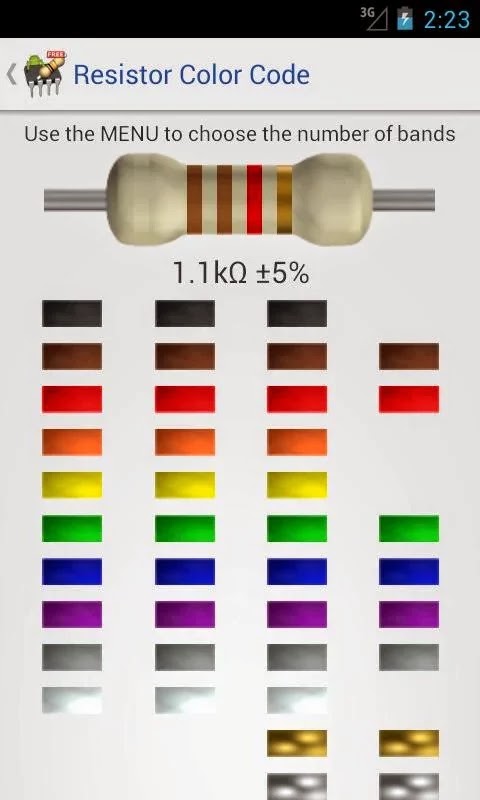
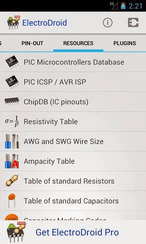
ElectroDroid is a simple and powerful collection of electronics tools and references.


Download Electrodroid free

2.Everycircuit

EveryCircuit is not just an eye candy. Under the hood it packs custom-built simulation engine optimized for interactive mobile use, serious numerical methods, and realistic device models. In short, Ohm's law, Kirchhoff's current and voltage laws, nonlinear semiconductor device equations, and all the good stuff is there.
Growing library of components gives you freedom to design any analog or digital circuit from a simple voltage divider to transistor-level masterpiece.
Schematic editor features automatic wire routing, and minimalistic user interface. No nonsense, less tapping, more productivity.


3.Engineering Handbook Lite

This is an amazingly useful and handy app for every engineering student.  It provides all the concepts of engineering and formulae and can also help in length mathematical calculations.


4.Droid Tesla

is another free app for simulating electronic circuits. This SPICE simulation tool is quiet similar to the app “EveryCircuit” mentioned above in its functionality - means you can build and simulate a circuit. But they both (EveryCircuit and DroidTesla) differ in user interface and features provided.


5.Electronics Tooolkit

is another free app which is a collection of simple tools like resistor color code calculator, series and parallel calculator etc. Almost all those tools are available in ElectroDroid app too, except for a Power Triangle calculator. I have listed this app here as it is free (and I have spent some time to download and test this app in my Galaxy) and you guys can try out, if you have time.More than 10,000 users have tried this application.


6.AllDataSheet app

This app is free version of the Datasheet website Alldatasheet.com. This app is nothing more than a book mark to alldatasheet website’s mobile version. I dont recommend you to download this app as your purpose will be served by visiting Alldatasheet.com from your mobile browser (which will get automatically redirected to mobile version) 


7.Logic simulator

Logic Simulator is a powerful tool for simulating logic circuits and testing how different gates can be used in a circuit,
It offers a big workspace and a simple menu system. It is perfect for education on a mobile platform.
To connect nodes you simply click on an output and then click on an input to connect it to.


8.Electronics Calculator

Simple electronics tools & calculators for your DIY projects.
Tools:
- Resistor Color Code (4,5 &6 band)
- Capacitor Conversion Calculator & Table
- Capacitor Code Converter (code to values - vica versa)
- Resistor in Series & Parallel
- Capacitor in Series & Parallel


Make piano using 555 IC

This circuit produces a tone according to the button being pressed. Only 1 button can be pressed at a time, that's why it is called a monophonic organ. You can change the 1k resistors to produce a more-accurate scale.Each button has a different tone , Moreover you can alter resistances to get soundsof your choice.

COMPONENTS USED :

1.555IC
2.Six1K resistances.
3.one 10K resistance
4.one 10uF Electrolytic capacitor
5.one 100nF Ceramic Capacitor
6.one 8ohm speaker
7.Six Push buttons(Tick-Tack buttons)
8.one 6-12V supply

The circuit below shows the arrangement neede for 555 piano:


STEPS :

1.Place 555 IC on BreadBoard
2.Connect pin 1 to ground.
3.Connect pin 8 and pin 4.
4.Connect pin 6 and pin 2.
5.Connect 100nF between pin 2 and ground.
6.Connect 10uF cap to pin 3 with Longer leg towards pin3.
7.Connect Shorter leg of the Cap above to one side of speaker, connect other side of speaker to ground.
8.Connect pin 8 to VCC.
9.Connect a 1k resistance between pin 7 and VCC.
10.Then connect a 10K variable resistor between pin 7 and one end of Push button, connect other end of push button to pin 6.
11.Then repeat connection of other buttons and 1K resistances as Shown in above Diagram.


(NOTE - In the circuit below i added  a LED between +ve and -ve terminal of battery to indicate if the piano is on or off , it is useful in case you want to make this ckt on a PCB , LED will help in indicating if piano is on and it can be switched off when not in use to save battery. A Switch can also be placed b/w the VCC and the ckt to switch piano on and off)


Machine Gun Sound Using 555 IC

This Circuit using 555 IC produces sound similar to a machine gun.It uses a combination of resistances and capacitances along with 555 IC which produces machine gun sound.


Components used:
1.one 555 IC
2.one BC557 Transistor
3.one 8ohm Speaker
4.two 10nF Ceramic Capacitors
5.one 100uF Electrolytic Capacitor
6.two 10uf Electrolytic Capacitor
7.one 100K resistor
8.one 33K resistor
9.one 6-12v power supply

Steps :
 1.Place 555 IC on BreadBoard.
 2.Connect pin 1 to ground.
 3.Connect pin 2 with pin 6.
 4.Connect pin 4 with pin 8.
5.Connect 10nF cap with one leg connected to pin 5 and other to ground.(ceramic cap do not have +ve and -ve side)
6.Connect a 10nf cap with one leg to pin 2 and other leg to ground.
7.Connect a 33k resistor with one leg at pin 2 and other at pin 3.
8.Place a BC557 on breadboard and connect emitter to VCC.
9.Connect a 100uF cap with longer leg to emitter and shorter one to collector.
10.Connect a 100K resistor between base of transistor and ground.
11.Again Connect a 10uF between Base of transistor and one terminal of speaker,with longer leg of cap towards Base.
12.Connect a 10uf cap between pin 3 of 555  and the same terminal of step 11. above.
13.Connect other terminal of speaker to VCC.
14.Connect pin 8 to VCC.
15.Power on the circuit and you are done.

( NOTE -- i didn't have a 33K resistor so i tried by putting 3x 10K resistors , 2x 1K resistors in series equaling to 32K, And i have also placed a push button between VCC and the circuit in order to get more machine gun like effect manually)


Ticking Bomb Sound Circuit using 555 IC

This circuit sound just like a ticking bomb.It utilizes the astable mode of 555 IC and produces ticks that are similar to a time bomb ticking.

Components Used:

1.one 555 IC
2.two 10uF Electrolytic Capacitor
3.one 47K ohm resistor
4.one 6-12 V power supply
5.one 8Ohm speaker


STEPS :
1.Place 555 IC on BreadBoard.
2.Connect pin 1 to ground(-ve terminal of battery)
3.Connect pin 2 with pin 6.
4.Connect pin 4 with pin 8.
5.Connect pin 8 with VCC (+ve terminal of battery)
6.Connect 47K resistor with one leg at pin 2 and another at pin 3.
7.Connect 10uF cap with longer leg(+ve ) to pin 2 and shorter leg(-ve ) to ground.
8.Now connect another 10uF cap with longer leg to pin 3 and shorter leg to a terminal of speaker,
and connect another terminal of speaker to ground. 
9.leave pin 5,7 as there is no use of them in this circuit.
10.Turn on Power to circuit and Enjoy the effect.


(NOTE - I didnt have 47K so i tested the circuit by putting series resistances equal to 40K)

Simple Motor Control using Arduino

We are first going to simply control the speed of a DC motor, in one direction, using a power transistor, diode, and external power supply to power the motor and a potentiometer to control the speed. Any suitable NPN power transistor designed for high current loads can replace the TIP120 transistor. However, I would highly recommend you use a power Darlington-type transistor. Make sure you choose a transistor that can handle the voltage and current your motor will draw. It may be necessary to fit a heat sink to the transistor if it is pulling more than about an amp.

The external power supply can be a set of batteries or a “wall wart”-style external DC power supply. The power source must have enough voltage and current to drive the motor. The voltage must not exceed that required by the motor. For my testing purposes I used a DC power supply that provided 5V at 500mA. This was enough for the 5V DC motor I was using. If you use a power supply with voltage higher than the motor can take, you may damage it permanently.


Connect It Up

First, make sure your Arduino is powered off by unplugging it from the USB cable. Now, take the required parts and connect them up as in Figure. It is essential for this project that you check and double check all of your connections are as they should be before supplying power to the circuit, as failure to do so may result in damage to your components or even your Arduino.


Enter the Code

Open up your Arduino IDE and type in the code

int potPin = 0; // Analog in 0 connected to the potentiometer
int transistorPin = 9; // PWM Pin 9 connected to the base of the transistor
int potValue = 0; // value returned from the potentiometer

void setup() {
// set the transistor pin as output:
pinMode(transistorPin, OUTPUT);
}
void loop() {
// read the potentiometer, convert it to 0 - 255:
potValue = analogRead(potPin) / 4;
// use that to control the transistor:
analogWrite(transistorPin, potValue);
}

Before uploading your code, disconnect the external power supply to the motor and ensure the potentiometer is turned fully counterclockwise. Now upload the code to the Arduino. Once the code is uploaded, connect the external power supply. You can now turn the potentiometer to control the speed of the motor.

Pulsating Lamp using Arduino

In this project we will alter the brightness of the LED, and make a pulsating lamp, using the analogWrite() function.

Parts Required

Table 3-3lists the parts required for Project 7. We simply use an LED and resistor.


Connect It Up

The circuit for this project is simply a green LED connecting, via a current-limiting resistor, between ground and Digital Pin 11.


Enter the Code

Open up your Arduino IDE and type in the code .

int ledPin = 11;
float sinVal;
int ledVal;
void setup()
 {
pinMode(ledPin, OUTPUT);
}
void loop() {
for (int x=0; x<180; x++)
 {
// convert degrees to radians then obtain sin value
sinVal = (sin(x*(3.1412/180)));
ledVal = int(sinVal*255);
analogWrite(ledPin, ledVal);
delay(25);
}
}

Verify and upload. You will now see your LED pulsate on and off steadily. Instead of a simple on/off state, we are now adjusting its brightness.

LED Chase Effect using Arduino

We are now going to use a string of LEDs (10 in total) to make an LED chase effect (see Table 3-1), similar to that used
on the car KITT in the KnightriderTV series or the Cylons in Battlestar Galactica.


Connect It Up

First, make sure your Arduino is powered off by unplugging it from the USB cable. Now take your breadboard, LEDs, resistors, and wires, and connect everything up as in Figure 3-1. Check your circuit thoroughly before connecting the power back up to the Arduino.


Enter the Code
Open up your Arduino IDE and type in the code .

 LED Chase Effect

byte ledPin[] = {4, 5, 6, 7, 8, 9, 10, 11, 12, 13}; // Create array for LED pins
int ledDelay = 65; // delay between changes
int direction = 1;
int currentLED = 0;
unsigned long changeTime;
void setup() {
for (int x=0; x<10; x++)
{
// set all pins to output
pinMode(ledPin[x], OUTPUT);
}
changeTime = millis();
}
void loop() {
if ((millis() - changeTime) > ledDelay)
{
// if it has been ledDelay ms since last change
changeLED();
changeTime = millis();
}
}
void changeLED()
 {
for (int x=0; x<10; x++)
{
// turn off all LED's
digitalWrite(ledPin[x], LOW);
}
digitalWrite(ledPin[currentLED], HIGH); // turn on the current LED
currentLED += direction; // increment by the direction value
// change direction if we reach the end
if (currentLED == 9) {direction = -1;}
if (currentLED == 0) {direction = 1;}
}

If you have done everything
correctly, you should now see the LEDs appear to move along the line, then bounce back to the start.

By changing the value of ledDelay, you can make the LED ping back and forth at different speeds. Try different
values to see what happens. You have to stop the program and manually change the value of ledDelay, then upload the amended code to see any changes.


Arduino cheatsheet!!


what is a Relay ?

A Relay is an electromagnetic device which is used to isolate two circuits electrically and connects them magnetically.
It is basically used in intrerfacing electronic circuit to an electric circuit. it means that a small DC voltage drives circuits working at large voltages like 230V AC (as in our homes).

A Relay consist of two parts
1. Input
2. Output

Input consist of a coil which gets energized when a voltage with appropriate magnitude is applied to it ( this voltage is known as Operating voltage). when the coil gets energized it generates a magnetic field which is responsible for the switching action of a relay.

Output consist of three contactors viz, NO,NC and COM.

NC- normally closed- In normal state or energized state the COM is connected to NC.
NO- normally open- In energized state COM gets connected to the NO.


When the DC voltage is applied at the input of relay the input coil gets energized by the applied voltage and generates magnetic field , this magnetic field switches over the COM contactor to NO
contactor. in this  way switching takes  place. and when the circuit gets denergized on the input side the COM is back to NC by a spring mechanism.

Types of relays-
1. DPDT
2.SPST
3.SPDT
4.DPST

DPDT- Double pole double throw - used to control two circuits , it has 6 pins. generally used in  robotics applications.

SPST- Single pole single throw - it is used for normal switching applications like ON/OFF.

SPDT- Single pole double throw- it is used for selecting "either" of the two power supplies. for eg. switching from 12V DC supply to 24V DC supply in a circuit.


what is Arduino ?

Arduino is an open-source electronics prototyping platform based on flexible, easy-to-use hardware and software. It's intended for artists, designers, hobbyists, and anyone interested in creating interactive objects or environments. This Google Code project is the home for the development of the Arduino platform. For more information on using Arduino, see the Arduino homepage.

The Arduino software consists of a development environment (IDE) and the core libraries. The IDE is written in Java and based on the Processing development environment. The core libraries are written in C and C++ and compiled using avr-gcc and AVR Libc. The source code for Arduino is now hosted on GitHub.

“Arduino is a single-board microcontroller designed to make the process of using electronics in
multidisciplinary projects more accessible. The hardware consists of a simple open-source hardware board designed around an 8-bit Atmel AVRmicrocontroller, though a new model has been designed around a 32-bit Atmel ARM.
The software consists of a standard programming language compiler and a boot loader that executes on the microcontroller.

 The Arduino board is made up of an Atmel AVR microprocessor, a crystal or oscillator (a crude clock that sends time pulses at a specified frequency to enable it to operate at the correct speed) and a 5V voltage regulator. (Some Arduinos may use a switching regulator, and some, like the Due, are not 5 volt). Depending on what type of Arduino you have, it may also have a USB socket to enable it to be connected to a PC or Mac to upload or retrieve data. The board exposes the microcontroller’s I/O (input/output) pins to enable you to connect those pins to other circuits or to
sensors, etc.
To program the Arduino (make it do what you want it to), you also use the Arduino IDE, which is a piece of free software that enables you to program in the language that the Arduino understands. In the case of the Arduino, the language is based on C/C++ and can even be extended through C++ libraries. The IDE enables you to write a computer program, which is a set of step-by-step instructions that you then upload to the Arduino. Your Arduino will then carry out those instructions and interact with whatever you have connected to it. In the Arduino world, programs
are known as “sketches”.

555 Timer LED Flashing circuit

This circuit uses the 555 timer in an Astable operating mode which generates a continuous output via Pin 3 in the form of a square wave. This turns the LED (D1) on and off. The speed at which the LED (D1) is turned on and off is set by the values of R1 and R2.

Components Required :

1x - 555  Timer IC
1x - LED (Any color )
1x - 470K Resistor
2x - 1K Resistor
1x - 1uF Electrolytic Capacitor
1x - 9V Voltage Battery


STEPS : 

1. Place the IC on your breadBoard , remember to put it in correct way else IC will burn.


2. Now connect the pin 1 to ground.
3. Connect the pin 2 with 6 and pin 4 with 8
4. Connect 1uF cap between pin 2 and ground, place long leng of capacitor towards the pin 2 and short leg towards ground.
5. Connect a resistance of 470K from pin 2 to 7 and connect a 1K resistance from pin 7 to VCC.
6. Connect pin 8 to VCC.
7. Connect a resistance of 1K from pin 3 to the longer leg of LED , then connect the shorter leg of LED to Ground.
8. Do not connect anything to pin 5 and leave it as it is.
9. Now just connect the Battery and enjoy the show.


Soldering on a perfboard

Carefully note the position of a component on your bread- board, and then move it to the same relative position on the perfboard, poking its wires through the little holes. Turn the perfboard upside down, make sure that it’s stable, and examine the hole where the wire is poking through, as shown in Figure below.

 A copper trace surrounds this hole and links it with others. Your task is to melt solder so that it sticks to the copper and also to the wire, forming a solid, reliable connection between the two of them. Take your pencil-style soldering iron in one hand and some solder in your other hand. Hold the tip of the iron against the wire and the copper, and feed some thin solder to their intersection. After two to four seconds, the solder should start flowing.


Allow enough solder to form a rounded bump sealing the wire and the copper, as shown in Figure below :


Wait for the solder to harden thoroughly, If all is well, snip the protruding wire with your cutters. See Figure below :

PerfBoard Errors :

 TOO MUCH SOLDER :

If the joint is thin, the wire can break free from the solder as it cools. Even a microscopic crack is sufficient to stop the circuit from working. In extreme cases, the solder sticks to the wire, and sticks to the copper trace around the wire, yet doesn’t make a solid bridge con- necting the two, leaving the wire encircled by solder yet untouched by it, as shown in Figure below. 


You may find this undetectable unless you observe it with magnification. You can add more solder to any joint that may have insufficient solder, but be sure to reheat the joint thoroughly. 


COMPONENTS PLACED INCORRECTLY :

It’s very easy to put a component one hole away from the position where it should be. It’s also easy to forget to make a connection. I suggest that you print a copy of the schematic, and each time you make a connection on the perforated board, you eliminate that wire on your hardcopy, using a highlighter.

All about Diodes

A diode is a very early type of semiconductor. It allows electricity to flow in one direction, but blocks it in the opposite direction. (A light-emitting diode is a much more recent invention.) Like an LED, a diode can be damaged by revers- ing the voltage and applying excessive power, but most diodes generally have a much greater tolerance for this than LEDs. The end of the diode that blocks positive voltage is always marked, usually with a circular band, while the other end remains unmarked. Diodes are especially useful in logic circuits, and can also convert alternating current (AC) into direct current (DC).

A Zener diode is a special type that  blocks current completely in one direction, and also blocks it in the other direction until a threshold voltage is reached.

Signal diodes are available for various different voltages and wattages. Like any semiconductor, they can overheat and burn out if they are subjected to mistreatment. The schematic symbol for a diode has only one significant variant: sometimes the triangle is outlined instead of filled solid black (see in Figure below).


What are capacitors?

DC current does not flow through a capacitor, but voltage can accumulate very quickly inside it, and remains after the power supply is disconnected. Figures below may help to give you an idea of what happens inside a capacitor when it is fully charged.


In most modern electrolytic capacitors, the plates have been reduced to two strips of very thin, flexible, metallic film, often wrapped around each other, separated by an equally thin insulator. Disc ceramic capacitors typically consist of just a single disc of nonconductive material with metal painted on both sides and leads soldered on. The two most common varieties of capacitors are ceramic (capable of storing a relatively small charge) and electrolytic (which can be much larger). Ceramics are often disc-shaped and yellow in color; electrolytics are often shaped like miniature tin cans and may be just about any color.

Ceramic capacitors have no polarity, meaning that you can apply negative volt- age to either side of them. Electrolytics do have polarity, and won’t work unless you connect them the right way around. The schematic symbol for a capacitor has two significant variants: with two straight lines (symbolizing the plates inside a capacitor), or with one straight line and one curved line, as shown in below.


 When you see a curved line, that side of the capacitor should be more negative than the other. The schemat- ic symbol may also include a + sign. Unfortunately, some people don’t bother to draw a curved plate on a polarized capacitor, yet others draw a curved plate even on a nonpolarized capacitor.