• Arduino

    Learn about Arduino and make various interesting projects using Arduino...

    Read More
  • 555 IC

    Learn about 555 IC and make various interesting projects using 555 IC...

    Read More
  • Basic Electronics

    Learn about Basic Electronics and various electronic components and their working...

    Read More
Showing posts with label LED. Show all posts

Heart Shaped Serial LED Flasher using 4017 and 555 IC

This circuit uses the 555 IC and 4017 IC to flash the LED's one by one placed in shape of a Heart shaped , hence named LED flasher circuit.
The 4017 is a decade counter which flashes the LED's one by one depending upon the clock signal received by it , here 555 produces clock signal and thus drives the 4017 IC to produce output at its pins.
The output LED's can be easily connected in a Heart Shape in order to Make a nice flashing Heart effect.This circuit can be made on a PCB and can be given to your loved ones , thus making it a perfect home made DIY electronic gift for your loved ones.

The speed of flashing can be controlled by the variable resitor , higher the value the slowly LED's will flash and slower the resistance value , the faster the LED's will Flash.
Also the Capacitacnce at pin 2 if 555 can be changed to get particular speed of flashing of LED's.

COMPONENTS REQUIRED :

1.one 555 IC
2.one 4017 IC
3.one 100k Resistor
4.one 100k Variable resistor
5.one 1uF Electrolytic capacitance
6.one 220R resistance
7.eight RED LED's
8.one 6-12v supply


Reaction Timer Game with 7 Segment

This is a game for two players. Player 1 presses the START button. This resets the 4026 counter chip and starts the 555 oscillator.
The 555 produces 10 pulses per second and these are counted by the 4026 chip and displayed on the 7-Segment display.
The second player is required to press the STOP button. This freezes the display by activating the Clock Inhibit line of the 4026 (pin 2).
Two time-delay circuits are included. The first activates the 555 by charging a 10u electrolytic and at the same time delivering a (high) pulse to the 4026 chip to reset it. The second timer freezes the count on the display (by raising the voltage on pin 2) so it can be read.


The speed with which the numbers change can be controlled by the capacitor at pin 2 of 555 IC or by changing the resistance between pin 2,3 of  555.
The value of capacitors can be 10uF,1uF,2.2uF and others can also be used but with 10uF the game is easy with 2.2uF its difficult and with 1uF its most difficult as the numbers change very fast so its difficult to stop at particular preselected number.

COMPONENTS USED  :

1.one Common Cathode 7 Segment
2.one 555 IC
3.one 4026 IC
4.two push buttons
5.three 10uF Electrolytic Capacitors
6.three 100k Resistances
7.one 68K Resistance
8.one 1nF Ceramic Capacitor
9.one 6-12v Power supply


Electronic Cricket Match Game using 555 IC and Decade Counter 4017

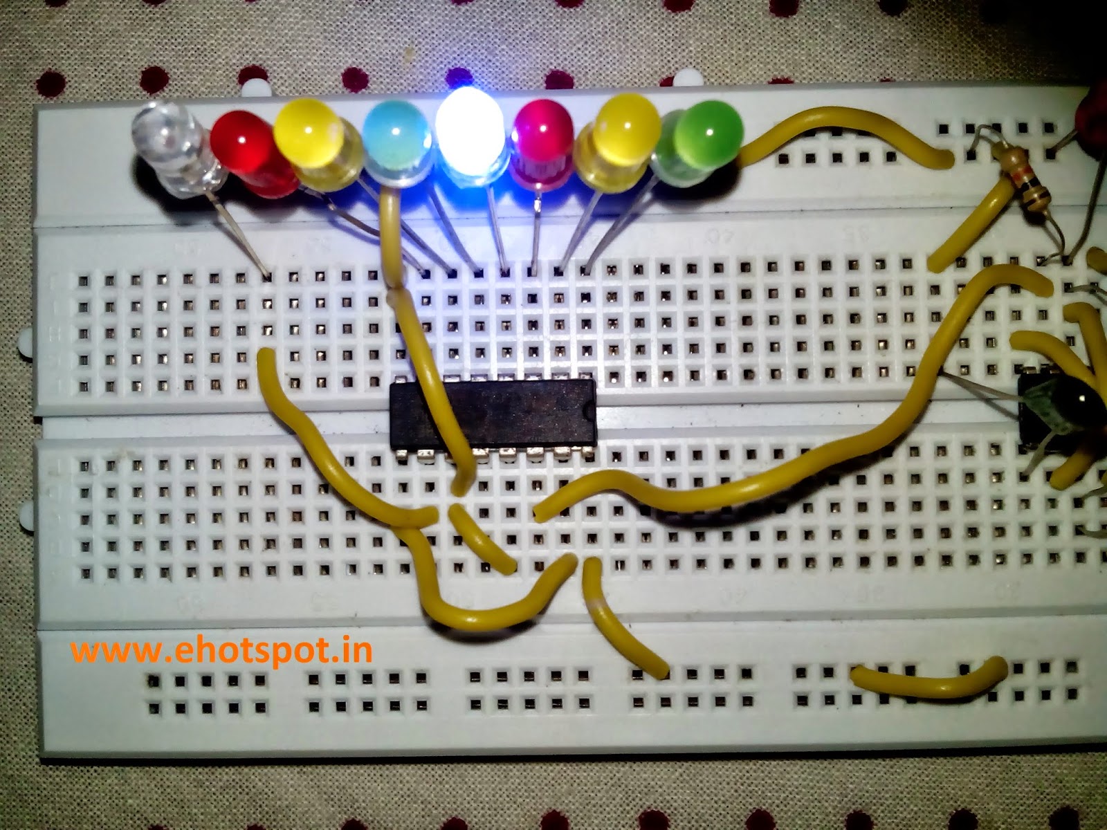
The Electronic Cricket Match game is presented below, the circuit has 8 LED which represent
 various states in a cricket game - 2 runs ,six ,bowled etc.

When the Push Switch S1 is pressed momentarily, the Astable operates and all the LEDs run very fast sequentially. When S1 is released, any one of the LED stands lit which indicates the status of the match. For example, if LED D7 remains lit, it indicates Sixer and if LED 8 remains lit, it indicates Catch out.
Label each LED for its status as shown in the diagram. Pressing of S1 simulates Bowling and Running LEDs indicates running of Batsman.

 IC1-555 is wired as an Astable Multivibrator with the timing elements R1, R2 and C1. With the shown values of these components very fast output pulses are generated from the Astable. Output from IC1 passes into the input of IC2 which is the popular Johnson Decade counter CD4017. It has 10 outputs. Of these 8 outputs are used. Output 9 ( pin9) is tied to the reset pin 15 to repeat the cycle. When the input pin 14 of IC2 gets low to high pluses, its output turns high one by one. Resistor R3 keeps the input of IC2 low in stand by state to avoid false indications.

COMPONENTS USED :

1.one 555 IC
2.one 4017 IC Decade Counter
3.two 12K resistances
4.one 10K resistance
5.one 100ohm resistance
6.one 1uF Electrolytic Capacitor
7.one 1nF Ceramic capacitor
8.Eight LED (different colors , if possible)
9.one Push Button
10.one 5-12v Supply

 ( NOTE - In Pics below i ommited the 100 ohm Resistor along along LED's as the voltage across LED's was 1.7v so there was no possibility of burning of LED's . Also The value of capacitor on pin 2 of 555 can be changed to higher value of 10uF to decrease the speed of sequential LED flashing when push button is pressed )


555 IC Tester Circuit

This simple 555 IC testing-circuit tests your entire 555 timer IC, so before using your IC check immediately that your IC is good or bad by checking it. This can be done by checking the IC that is it is oscillating or not. Or you can use this circuit in some other circuits also to troubleshoot the proper working of 555 IC.

First of all insert the IC in socket very carefully so that no pin of 555 timer get damage. Now to see the result, switch on the power supply. 
If your 555 timer is working properly, both the LED1 and LED2 will glow.
And any of the LEDs is off or both LED1 and LED2 are not glowing means your 555 timer IC is faulty.


COMPONENTS USED :

  • one 555 IC
  • one 68K Resistance
  • one 39K resistance
  • two 220ohm resistance
  • one 1uF Electrolytic capacitor
  • one 1nf Ceramic capacitor
  • two LED's (any color)


Drakness Detector using 741 opamp IC

The circuit below is darkness detector that is it automatically turns on the LED when LDR senses no light.
LDR is the light dependent resistor when exposed to darkness, a LDR has a tremendous amount of resistance. Depending on the specific LDR in use, its resistance can be anywhere from over 100KΩ to well over 2MΩ. When exposed to bright light, a LDR's resistance drops drastically. Again, based on the LDR, it may be to 5KΩ or below or to about 30KΩ. For any LDR, you can pretty much be sure that the resistance will fall to about 30KΩ when exposed to bright light.


COMPONENTS REQUIRED :

1.one LM741 IC
2.one LDR
3.Two 100k resistances
4.one 180ohm resistance
5.one 4.7k resistance
6.one LED
7.one 9-12v Battery


what are Infrared LEDs ?

Infrared LEDs are just like ordinary LEDs but the light output cannot be seen. To view an infrared LEDs, turn it on with the appropriate battery and dropper resistor and view it with a camera. You will see the illumination on the screen.

Infrared LEDs are sometimes clear and sometimes black. They operate just like a red LED with the same characteristic voltage-drop of about 1.7v.

Sometimes an infrared LED is pulsed with a high current for a very short period of time but the thing to remember is the wattage-dissipation of a 5mm LED is about 70mW. This means the constant-current should be no more than 40mA.

 Infrared LEDs are also called TRANSMITTING LEDs as they emit light. These are given the term Tx (for transmitting). An infrared LED can be connected to a 5v supply via a 220R current-limiting resistor for 15mA current.
 Infrared receivers (Rx) can look exactly like infrared LEDs, but they do not emit IR light. They detect Infrared illumination and must be connected the correct way in a circuit.
They have a very high resistance when no receiving IR illumination and the resistance decreases as the illumination increases.
This means they are connected to a 5v supply via a resistor and when the resistance of the infrared receiver decreases, current will flow thought it and the resistor. This will produce a voltage across the resistor and this voltage is fed to the rest of the circuit.

Here is a circuit to show how to connect an infrared LED and Infrared (diode) receiver:


You cannot use an IR LED as a receiver or an Infrared diode as an illuminator. They are constructed differently. An infrared LED has a characteristic voltage drop of 1.7v An Infrared receiver does not have a characteristic voltage-drop. It has a high resistance when not illuminated and a low resistance when it receives illumination.
 

Laser Ray Effect using 555

This circuit produces a weird "Laser Ray" sound and flashes a  LED at approx 5Hz.

 COMPONENTS USED:

1.one 555 IC
2.one 100nF Ceramic Capacitor
3.one 10uF Electrolytic Capacitor
4.one 220K resistance
5.one 470ohm resistance
6.one LED
7.one 8ohm Speaker
8.one 6-12v supply


Delayed Start Circuit using 555 IC

This circuit does not turn on for XX seconds after power is applied. Adjustable from 1 second to 2 minutes.The delay can be adjusted by changing the resistance between pin 6 and ground.
Either you can use a 1M Variable Resistor or use different resistances to get different delays in turning on the circuit. Just Connect a LED to pin 3 of 555 along with a resistor to delay the start of LED.

Resistances Between pin 6 and Ground and their Respective Delays :

1K-     1s
100k-  10s
220k-  25s
250k-  27s
500k-  56s
1M-   2min


COMPONENTS USED :

1.one 555 IC.
2.one 100uF Electrolytic Capacitor.
3.one 1M Variable resistor or different Resistances (1K,100K,250K etc)
4.one LED.
5.one 470ohm/220ohm resistance.
6.one 9-12V Power Supply.


Toggle LED on off using 555

This circuit will toggle the output each time the switch is pressed. The action cannot be repeated until the 10u charges or discharges via the 100k. In this Project we will connect an LED to the pin 3 of 555,when the button will be pressed the LED will toggle on off.

COMPONENTS REQUIRED :

1.one 100k Resistor
2.two 10k Resistor
3.one 555 IC
4.one 10uF Electrolytic capacitor
5.one push button
6.one 470ohm/220ohm resistor
7.one LED
8.one 9-12V supply

STEPS  :

1.Place 555 IC on BreadBoard
2.Connect pin 2 to pin 6.
3.Connect pin 4 to pin 8.
4.Connect pin 1 to ground.
5.Connect pin 8 to VCC.
6.connect a 10K resistor between pin 2 and ground.
7.Connect another 10k resistor between pin 6 and VCC.
8.Connect 100K resistor between pin 3 and longer leg of Capacitor.
9.Connect shorter leg of Capacitor to ground.
10.Connect an LED to pin 3 with a 470ohm/220ohm resistor in series.
11.Connect the push button between pin 6 and positive terminal of Capacitor.
12.Connect power supply


LED Fading/Blinking using 555 IC

This circuit makes a LED fade on and off.  first charges a 100u and the transistor amplifies the current entering the 100u and delivers 100 times this value to the LED via the collector-emitter pins. The circuit needs 9v for operation since pin 2 of the 555 detects 2/3Vcc before changing the state of the output so we only have a maximum of 5.5v via a 470R/220R resistor to illuminate the LED.


COMPONENTS REQUIRED:

1. one 470ohm / 220ohm  resistor 
2. one 33k resistor
3. one LED ( I used Blue)
4. one 100uf Capacitor
5. one 555 Timer
6. one Generic NPN Transistor (2222A)
7. one 9-12V Supply

STEPS :

1. Place 555 Timer
2. Connect Pin 1 To Ground
3. Connect Pin 2  to Base of NPN
4. Connect 33K resistor between Pin 3 and base of NPN
5. Connect Pin 4 to Pin 8
6. Connect Pin 6  to Pin 2
7. Connect Pin 8  to Positive voltage
8. Connect Emitter of NPN to 470ohm resistor to longer leg of LED,Connect shorter leg to ground
9. Connect Base of NPN to + side of cap, then ground - side
10. Connect Collector of NPN to + voltage


Resistance b/w pin3 of 555 and base of NPN(2222A)

30K/33K - Fadein,Fade out
220ohm - Fast blink
1K - Blink
470ohm - Slow blink
100K - Faded start


(NOTE :  Below i used a combination of resistors equal to 30K  to Fade in and Fade out a LED )


Transistor Tester using 555 IC

The 555 operates at 2Hz. Output pin 3 drives the circuit with a positive then zero voltage. The other end of the circuit is connected to a voltage divider with the mid-point at approx 4.5v.

This allows the red and green LEDs to alternately flash when no transistor is connected to the tester.

If a good transistor is connected, it will produce a short across the LED pair when the voltage is in one direction and only one LED will flash.

If the transistor is open, both LED’s will flash and if the transistor is shorted, neither LED will flash.

COMPONENTS USED  :

1.one 555 IC
2.two 1N4148 diode
3.one 33K resistor
4.four 220 Ohm resistance
5.one Red LED
6.one Green LED
7.one 10uF Electrolytic Capacitor
8.one 9-12v Supply


(NOTE - In pics below i have used a series of resistances to make 33K resistance )


Making Traffic Lights using 555 IC

Here's a clever circuit using two 555's to produce a set of traffic lights for a model layout.  The red LED has an equal on-off period and when it is off, the first 555 delivers power to the second 555. This illuminates the Green LED and then the second 555 changes state to turn off the Green LED and turn on the Orange LED for a short period of time before the first 555 changes state to turn off the second 555 and turn on the red LED.
A supply voltage of 9v to 12v is needed because the second 555 receives a supply of about 2v less than rail.
This circuit also shows how to connect LEDs high and low to a 555 and also turn off the 555 by controlling the supply to pin 8. Connecting the LEDs high and low to pin 3 will not work and since pin 7 is in phase with pin 3, it can be used to advantage in this design.

Here is a further description of how the circuit works:

 Both 555's are wired as oscillators in astable mode and will oscillate ALL THE TIME when they are turned ON. But the second 555 is not turned on all the time! The first 555 turns on and the 100u is not charged. This makes output pin 3 HIGH and the red LED is not illuminated. However the output feeds the second 555 and it turns on.

  Output pin 3 of the second 555 turns on the green LED and the second 100u charges to 2/3 rail voltage and causes the 555 to change states. The green LED goes off and the orange LED turns on. The second 100u starts to discharge, but the first 100u is charging via a 100k and after the orange LED has been on for a short period of time, the first 555 changes state and pin 3 goes LOW.

This turns on the red LED and turns off the second 555.
The first 100u starts to discharge via the 100k and eventually it changes state to start the cycle again.

The secret of the timing is the long cycle-time of the first 555 due to the 100k and the short cycle due to the 47k on the second 555.

COMPONENTS USED :
1.Two 555 IC.
2.Two 100uF cap.
3.one 100K resistance.
4.one 47K resistance.
5.one 470ohm resistance.
6.Two 220ohm resistance.
7.one red LED.
8.one orange LED.
9.one green LED.
10.one 6-12V power Supply.


(NOTE - i didnt had a 47k resistances so i used a series of resistances to make 47k resistance, and i also used double LED's ,two green ,two red,two yellow. Just place 2nd LED in parallel with the LED in the circuit and you are done.!)